

Clarify the machining requirements before submitting drawings
In custom aluminum profile machining, rework is often caused not by insufficient machining capability, but by incomplete information in the drawings. Dimensions may be specified, but datums omitted; hole positions may be marked, but tolerances left undefined; the profile may be selected, but the machining direction not indicated. Once production begins, these omissions turn into communication costs, production-scheduling delays, and assembly deviations.
Industrial aluminum profiles are commonly used for equipment frames, safety guards, conveyor lines, and workbenches. The requirements for custom aluminum profile machining vary from one application to another. Two structures that look similar may have very different priorities: one may require high assembly accuracy, while the other may need more room for on-site modifications. Confirming the key parameters before submitting the drawings can make delivery much smoother.
Shanghai Xiangda Industrial Aluminum Profile Co., Ltd. has long served projects in industrial automation, smart manufacturing, and equipment manufacturing. With a standardized production and machining system established in Songjiang, Shanghai, the company handles everything from profile selection and cutting and drilling to assembly and supporting services. Its core expertise is not simply being able to machine profiles, but translating drawing requirements into stable, executable process conditions.
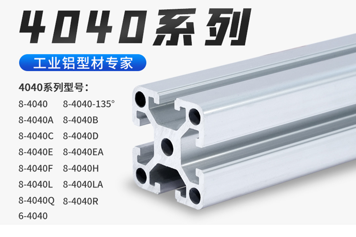
When confirming dimensions for actual use, do not focus only on the overall length
Many drawings specify the profile length first, but in custom aluminum profile machining, the overall length is only a starting point. More important is the role the profile plays in the structure: is it a crossbeam, a column, a door frame, or a mounting edge for a guide rail? The dimensional control priorities vary according to its position.
For example, equipment frames require particular attention to the squareness of multiple assembled profiles. If the length error of each profile accumulates, the result may be uneven diagonals. For conveyor support beams, the relationship between mounting holes and the end face is more important, because motor mounts, support plates, and connectors are usually assembled from a common datum.
Confirm these dimensions separately
- Finished overall length: specify whether it includes an allowance for trimming the cut ends.
- Distance from the machining datum to the hole center: do not specify only the distance between holes; also identify the reference point.
- Distance from the end face to a slot, notch, or step: this affects the assembly of subsequent connectors.
- Dimensions for component fit: identify left-right symmetrical parts and front-back mirrored parts separately.
If commonly used profiles such as 3030, 4040, or 4080 are selected, it is easy to assume that all standard profiles are much the same. But once custom cutting, drilling, tapping, or CNC machining is involved, the dimensional chain is no longer determined by the profile alone. It is jointly determined by the datum, process steps, and assembly method.
Even for the same hole position, the priorities differ completely by application
Hole positions are one of the most common causes of rework in custom aluminum profile machining. The issue is usually not whether a hole is present, but what it is positioned relative to, what will be installed afterward, and whether on-site adjustment is allowed.
In safety guard projects, deviations in hole positions can directly affect the installation of door panels, hinges, and locks, resulting in uneven gaps. For conveyor lines or automation equipment supports, hole-position deviations can affect motors, sensors, guide rails, and other components, making them difficult to install, requiring holes to be enlarged, or causing stress after forced assembly.
If a drawing only specifies “drill Φ8, one on each side,” the machining team still cannot determine whether to locate the holes from the end face or the centerline. A more reliable approach is to specify the hole diameter, depth, quantity, spacing, reference edge, and orientation all at once.
Set tolerances based on the assembly method, not by making them as tight as possible
Some drawings apply tight tolerances across the board to critical dimensions, assuming that smaller tolerances are always safer. In practice, tolerances for custom aluminum profile machining should be set according to the application. A frame secured with connectors and a machined part that directly fits a precision component do not have the same tolerance requirements.
For equipment frames, it is often sufficient to control cutting-length and hole-position tolerances appropriately. Pursuing extreme precision unnecessarily only increases machining difficulty and cost. By contrast, if guide rails, cylinder mounts, or fixture locating blocks need to be installed on the profile, tighter requirements should be set separately for the relevant local dimensions and hole positions; standard frame tolerances should not be applied by default.
Practical ways to assess tolerances
- First distinguish between cosmetic, structural, and functional dimensions.
- Apply tighter tolerances only to dimensions that affect assembly and operation.
- For batch parts requiring interchangeable assembly, standardize the tolerances rather than relying on manual fitting.
- If on-site adjustment is possible, tolerances can be relaxed appropriately to achieve better value for money.
This is also why many projects begin with small-batch validation at the sample stage. Common industrial aluminum profile models such as XD-8-3030L have a wide range of applications, but the final tolerance strategy still needs to be determined based on the specific structure and installation method.
Equipment frames, safety guards, and conveyor lines have different drawing priorities
In actual projects, a common misjudgment is to treat similar-looking structures as having the same machining requirements. Even when both use industrial aluminum profile frames, the priorities for equipment bodies and perimeter guards may be completely different.
Equipment frames depend more on overall datums
These applications generally require structural stability, continuous mounting surfaces, and ease of future expansion. Before submitting the drawings, confirm the datum end, joint relationships, consistent column heights, and whether provision is needed for cable ducts, panel mounting holes, and caster or leveling-foot connections.
Safety guards depend more on opening operation and visual fit
Door frames, viewing windows, cover panels, and seals often need to fit together. Even a slight hole-position deviation can lead to uneven door gaps or misaligned latches. It is not enough to specify accurate hole-center dimensions; the orientation of left and right parts, hinge mounting surfaces, and the relationship between the cover panel and its edge also need to be clearly indicated.
Conveyor structures depend more on continuity at interfaces
Legs, brackets, and drive mounting positions on conveyor lines often need to connect with other equipment. If the drawings specify only individual parts without checking the elevation, center distance, and mounting pitch of the entire line, individual components may fit while the overall assembly does not.
What is easy to overlook goes beyond the dimensions themselves
Delays in many custom aluminum profile machining projects are not caused by an incorrect dimension, but by drawings that do not fully define the machining requirements. For example, tapping depth may be unspecified, the sequence of surface treatments may be unclear, or the need to chamfer profile end faces may not be indicated. Any of these can affect subsequent assembly and appearance.
- No datum surface is defined, leading to different interpretations of the same dimension.
- Through holes, blind holes, countersinks, and tapped holes are not distinguished.
- The profile slot orientation is overlooked, and the parts are found to be reversed during on-site assembly.
- Only two-dimensional dimensions are provided, with no explanation of the three-dimensional installation relationship.
- Sample requirements are applied directly to batch parts without assessing process stability.
For projects involving cutting, drilling, tapping, CNC machining, and assembly, the value of one-stop service lies precisely in addressing these issues. A machining team familiar with industrial automation applications can often identify missing information in the drawings in advance, reducing the need for later disassembly and modifications. This is one of the practical advantages Shanghai Xiangda has developed through projects in the Yangtze River Delta.
Before submitting drawings, check them again using these steps
At the final stage of drawing preparation, there is no need to make every detail overly complex, but the key information must be complete. A more effective approach is to move beyond asking “Can this be machined?” and ask “Can it be machined correctly the first time?”
- First confirm that the profile specifications, lengths, quantities, and orientation markings are consistent.
- Then check that every hole position is dimensioned from a clearly defined datum.
- Circle the tolerances requiring particular control instead of applying the same level of control everywhere.
- Check the interfaces for accessories, such as corner brackets, nuts, cover panels, and caster mounting methods.
- For batch machining, confirm the sample standard and acceptance criteria in advance.
If the structure uses XD-8-3030L or other commonly used industrial aluminum profile models, it is also advisable to check the accessory system and slot compatibility at the same time. This helps prevent a situation where the drawings are correct but the assembly accessories do not fit.
Putting the application, dimensions, tolerances, hole positions, and datums together in one review table is often more effective than simply changing an individual value. A systematic review before submitting the drawings can identify potential issues earlier and help control the lead time, cost, and finished-product consistency of custom aluminum profile machining.
Related News
- ▶ Moving Forward Together, Achieving Shared Success | On October 10, Shanghai Xiangda Industrial Aluminum Profiles welcomed customers and partners for a visit and inspection
- ▶ Why Do Custom Aluminum Extrusion Die-Opening Prices Vary So Widely? What Are the Key Factors Affecting the Quote?
- ▶ How to Choose Between 6063 and 6061 Alloys for Custom Aluminum Extrusion Dies?
Leave a Message Online


Thank you very much for writing to us. Please leave your message and contact information, we will reply to you within 24 hours.